How to connect the solenoid valve to the double-stroke cylinder?A two-stroke cylinder requires several solenoid valves
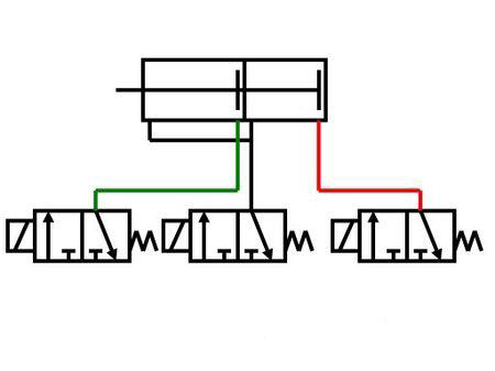
1. A double-stroke cylinder generally requires two solenoid valve coils, which are respectively responsible for the forward and reverse operation of the cylinder. By using the TPC4-4TD controller, In cooperation with the sensor switch, thecylinder can be positioned at any position in the stroke.
2. If there is no need to control the stroke of the cylinder, a single-coil two-position five-way cylinder solenoid valve is usually used. The solenoid valve extends to the electric cylinder and retracts when the power is turned off. . You can refer to the picture below: This is a universal wiring diagram, which can control any action of the cylinder and realize control functions of various actions such as automatic, manual, and cycle.

Double-stroke cylinder working control principle diagram
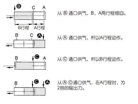
1. There are two working principles of double-stroke cylinders. The first is a special double-stroke cylinder with 3 ports, ABC port, A in, B out, C in, which is the stroke. 1. A goes out, B goes in, C goes in, which is the itinerary 2.
There is also a cylinder with two chambers separated inside, each with a piston, and the length of one piston rod is longer than the other two, which is equivalent to being connected in series. For 4 ports, just use two five-way valves, but you may need to use a reversible pressure regulating valve.
2. Commonly used solenoid valves can be of various types such as two-position two-way, two-position three-way, two-position four-way, three-position four-way and three-position five-way. . The three-position means that the valve core can be in three positions, and the five-way means that the number of interfaces is five. The connection status of each interface is different in different positions of the valve core. There are three holes on one side, the middle one is connected to the intake pipe, the two on both sides are installed with mufflers (air valves), and the two holes on the other side are connected toCylinder.

How the solenoid valve works
There is a closed cavity in the solenoid valve, with through holes at different positions. Each hole is connected to a different oil pipe. There is a piston in the middle of the cavity and two electromagnets on both sides. When the magnet coil on the surface is energized, the valve body will be attracted to that side, and different oil drain holes can be opened or closed by controlling the movement of the valve body.
The oil inlet hole is always open, and the hydraulic oil will enter different oil discharge pipes, and then push the piston of the oil cylinder through the pressure of the oil, which in turn drives the piston rod, and the piston The rod drives the mechanism. In this way, the mechanical movement is controlled by controlling the current on and off of the electromagnet.


 WhatsApp: +8615857777578