1. General wiring method
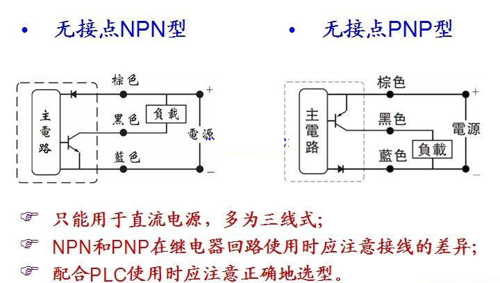
When using a three-wire induction switch, be sure to use a DC power supply. Pay attention to the black wiring. Wrong connection will cause the switch to burn out;the brown wire should be connected to positive potential, and the blue wire should be connected to positive potential. The colored wire is connected to the negative potential, and the black wire is connected to the load in series and then connected to the positive potential.
2. Series connection method
When using sensor switches in series, it should be noted that the internal voltage drops of the sensor switches also add up. The internal voltage drop of each sensor switch is about 1.5V;when too many sensor switches are connected in series When the total internal voltage drop of the induction switch is too large, the load may not operate;the number of switches that can be connected varies depending on the power supply voltage.
3. Parallel connection
When inductive switches are used in parallel, it does not affect the action of the inductive switch and the load output, but the trace output leakage current will add up;when too many inductive switches are connected in parallel time, and if the load current is too small, the load output may malfunction;the number of switches that can be connected in parallel varies depending on the load current.
Cylinder magnetic switch wiring diagram
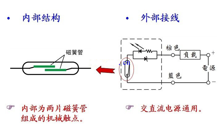
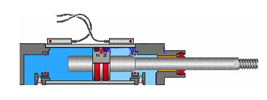
The cylinder magnetic switch is used to detect the position of the cylinder piston, that is, to detect the movement stroke of the piston. It can be divided into two types: contact type (reed tube type with contacts) and contactless type (transistor type without contacts).
The contact reed tube type has a mechanical contact composed of two reed tubes inside, and is suitable for AC and DC power supplies.

DangsuiCylinder When the moving magnetic ring approaches the induction switch, the two magnetic reeds of the induction switch It is magnetized to close the contacts and generate an electrical signal;when the magnetic ring leaves the magnetic switch, the reed loses magnetism and the contacts openopen, generating an electrical signal. disappear. In this way, the piston position of the cylinder can be detected to control the corresponding solenoid valve action.

Non-contact transistor type-NPN and PNP types can only be used for DC power supply, most of which are three-wire types;when using NPN and PNP in relay circuits, you should pay attention to the wiring differences;cooperate Pay attention to correctness when selecting PLC
Ground selection.

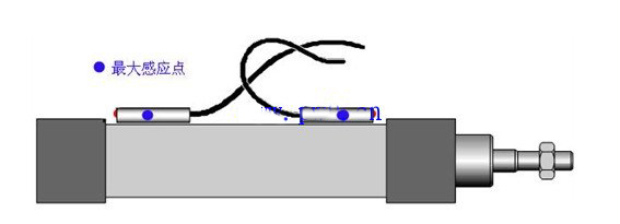
The contactless sensor switch is essentially different from the contact sensor switch in structure and principle. It sends control signals by controlling the internal transistor. When the magnetic ring is close to the sensor switch
, the transistor turns on and generates an electrical signal;when the magnetic ring leaves After the magnetic switch, the transistor turns off and the electrical signal disappears. The maximum sensing point is as shown below.


 WhatsApp: +8615857777578