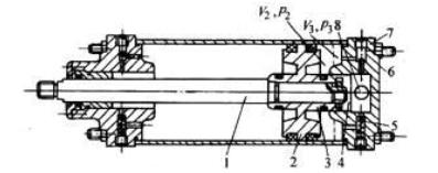
Cushion CylinderFor high speedcylinders, if necessary measures are not taken, the piston will hit the end cover with great force (energy), causing vibration and damaging the parts. In order to make the piston move smoothly at the end of the stroke without causing impact. Buffer devices are added at both ends of the cylinder, which are generally called buffer cylinders. The internal structure of the buffer cylinder is shown in the figure, which is mainly composed of piston rod, piston, buffer plunger, one-way valve, throttle valve, end cover, etc.

Buffer cylinder internal structure diagram
1—Piston rod;2—Piston;3—Buffer plunger;4—Plunger hole;5—One-way valve 6—Throttle valve;7—End cover;8—Stomata
Working principle of buffer cylinder: When the piston is pushed to the right by compressed air During movement, the gas in the right chamber of the cylinder is discharged through the plunger hole 4 and the air hole 8 on the cylinder head. When the piston moves near the end of its stroke, the buffer plunger 3 on the right side of the piston blocks the plunger hole 4. When the piston continues to move to the right, the remaining gas sealed in the right chamber of the cylinder is compressed and slowly passes through the throttle valve 6. And the air hole 8 is discharged. If the pressure generated by the compressed gas is balanced with all the energy of the piston movement, a buffering effect will be achieved, so that the piston moves smoothly at the end of the stroke without impact. By adjusting the opening of the throttle valve 6, the exhaust volume can be controlled, thereby determining the pressure in the compressed volume (called the buffer chamber) to adjust the buffering effect. If the piston is moved in the reverse direction, compressed air is input from the air hole 8 to directly open the one-way valve 5 and push the piston to move to the left. If the opening of throttle valve 6 is fixed and cannot be adjusted, it is called a non-adjustable buffer cylinder.
There are many types of buffer devices installed in the cylinderThe above is just one of them. Of course, measures can also be taken on the pneumatic circuit to achieve the purpose of buffering span>


 WhatsApp: +8615857777578