Locked cylinderA cylinder that is not particularly commonly used. This cylinder has three air inlets. , so compared with ordinary cylinders, the control loop is quite different.
Structural principle:
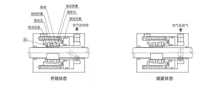
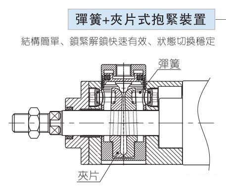
The structural principle of the locking cylinder is shown in the following two figures. In Figure 1, the spring force acts on the conical ring and is transmitted to the brake shoe seat through the steel ball, and then to the brake pad. Moving tiles, due to the wedge effect, act onbelt locks The braking force of the cylindershaft is very large. After the air is supplied to the unlocking port, the conical ring overcomes the spring force and moves to the left under the action of air pressure, causing the steel ball to break away from the conical ring and releasing the braking force. The basic principle in Figure 2 is the same, except that the holding method is changed to the clip type.


Control loop:
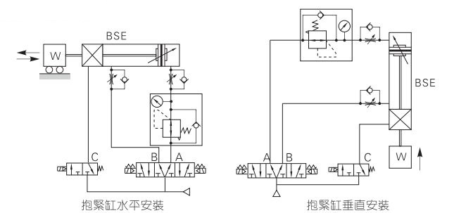
Generally, the cylinder is controlled by a two-position solenoid valve, because the cylinder only has two positions. The three-position solenoid valve is used to deal with the cylinder that needs to maintain a special position when the power is suddenly cut off. Locked cylinders need to be controlled by at least two solenoid valves, as shown in the following figure for horizontal transportation:

1) The solenoid valve that controls the forward and backward movement of the cylinder is a three-position five-way middle-sealed solenoid valve, in which a one-way valve is added between the solenoid valve on the extension side of the cylinder and the speed control valve. Parallel pressure regulating valve;
2) The solenoid valve that controls the locking is a two-position three-way solenoid valve. The two-position three-way solenoid valve is suitable for controlling the air path of a single interface, such as a single-acting cylinder, a blower Qi, etc.;
3) Since the force value of cylinder extension is greater than the force value of retraction (provided that the extension and retraction loads are the same), it is necessary to add a pressure regulating valve and a one-way valve, that is, Adjust the extended force value to equal the retracted force value;
4) The cylinder is placed horizontally, but because the load is large when the cylinder is extended and small when it is retracted, the pressure regulating valve should be addedCylinder returns to the side air path to ensure sudden The movable platform will not fall suddenly when the power is cut off.


 WhatsApp: +8615857777578