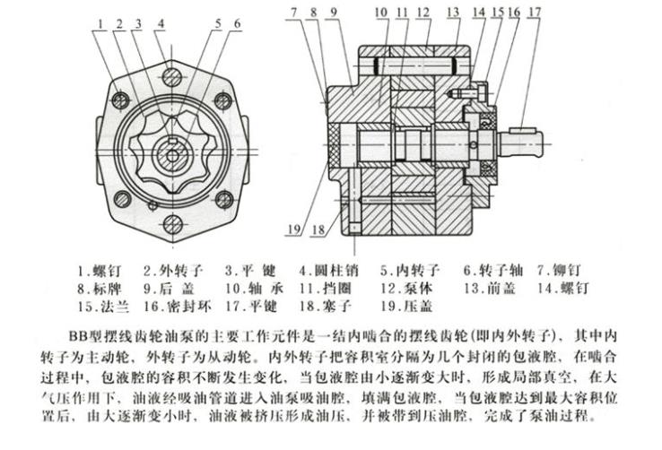
In terminology, a gear pump is also called a positive displacement device, that is, like a piston in a cylinder, when one tooth enters the fluid space of another tooth, the liquid being mechanically squeezed out. Because liquid is incompressible, the liquid and the teeth cannot occupy the same space at the same time, so the liquid is expelled. Due to the continuous meshing of the teeth, this phenomenon continues to occur, thus providing a continuous discharge volume at the outlet of the pump. The discharge volume is the same every time the pump rotates. As the drive shaft rotates continuously, the pump discharges fluid continuously. The flow rate of the pump is directly related to the speed of the pump.

In fact, there is a very small amount of fluid loss in the pump, which prevents the hydraulic gear pump from operating at 100% efficiency, because this fluid is used to lubricate the bearings and gears Both sides, and the pump body can never fit without clearance, so 100% of the fluid cannot be discharged from the outlet, so a small amount of fluid loss is inevitable. However, the pump can still operate well and can still reach 93% to 98% efficiency for most extruded materials. This type of pump will not be affected much by fluids whose viscosity or density changes during the process. If there is a damper, such as a strainer or a restrictor placed on the side of the discharge port, the pump will push the fluid through them. If this damper changes during operation, that is, if the filter becomes dirty, clogged, or the back pressure of the limiter increases, the pump will maintain a constant flow rate until the mechanical limit of the weakest component of the unit is reached. (Usually equipped with a torque limiter).
There is actually a limit to the speed of a pump, which mainly depends on the process fluid. If oil is delivered, the pump can rotate at a very high speed. , but this limitation is greatly reduced when the fluid is a high-viscosity polymer melt.
It is very important to push the high-viscosity fluid into the space between the two teeth on the side of the suction port. If this space is not filled, Hydraulic gear pump cannot discharge accurate flow , so the PV value (pressure × flow rate) is also another limiting factor and a process variable. Due to these limitations, gear pump manufacturers will provide a range of products, that is, different specifications and displacement (the amount discharged per revolution). These pumps will be matched to the specific application process to optimize system capabilities and price.


 WhatsApp: +8615857777578