Hydraulic gear pumps mainly include: high-pressure fixed gear pump, high-pressure double gear pump, lubrication pump, chemical pump, two-way gear motor, gear pump with pressure regulating valve, gear pump with Lift valve.
The working principle and structural composition of the gear pump
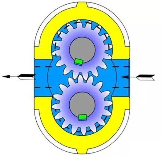
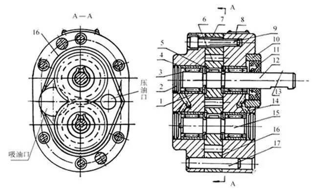
The working principle of the gear pump is shown in the figure below. It is a three-piece structure. The three pieces refer to the pump cover 4, 8 and the pump body. 7. The pump body 7 is equipped with a pair of gears 6 with the same number of teeth, close to the width of the pump body and meshing with each other. This pair of gears, the two end covers and the pump body form a sealed cavity, and the seal is sealed by the tooth tops and meshing lines of the gears. The chamber is divided into two parts, namely the oil suction chamber and the oil pressure chamber. The two gears are respectively fixed on the driving shaft 12 and the driven shaft 15 supported by needle bearings with keys, and the driving shaft is driven to rotate by the electric motor.

The structure of the gear pump is shown in the figure below. When the driving gear of the pump rotates in the direction of the arrow in the figure, the right side of the gear pump (suction chamber) The gears are disengaged, and the gear teeth exit between the teeth, which increases the sealing volume and forms a partial vacuum. The oil in the tank enters between the teeth through the oil suction pipeline and the oil suction chamber under the action of external atmospheric pressure. As the gear rotates, the oil sucked between the teeth is brought to the other side and enters the oil pressure chamber. At this time, the gear teeth enter into mesh, so that the sealing volume gradually decreases, and the oil in the part between the gears is squeezed out, forming the oil pressure process of the gear pump. When the gear meshes, the tooth contact line separates the oil suction chamber and the oil pressure chamber, which plays the role of oil distribution.

WhenGear pump When the driving gear of the gear pump is continuously rotated by the motor, the gear teeth disengage from the meshing side. As the sealing volume increases, oil is continuously sucked from the oil tank. The gear teeth Entering the meshing side, oil is continuously discharged due to the reduction in sealing volume. This is the working principle of the gear pump. The front and rear covers of the pump and the pump body are positioned by two positioning pins 17 and fastened with 6 screws as shown in Figure 3-3. In order to ensure that the gear can rotate flexibly while ensuring minimal leakage, there should be an appropriate clearance (axial clearance) between the gear end face and the pump cover. The axial clearance for small flow pumps is 0.025~0.04mm, and for large flow pumps 0.04~0.06mm. The gap (radial gap) between the tooth top and the surface of the pump body has a small impact on leakage due to the long sealing belt and the shear flow formed by the tooth top linear velocity and the direction of oil leakage. The problem is: when the gear is subjected to an unbalanced radial force, the tooth top should avoid collision with the inner wall of the pump body, so the radial gap can be slightly larger, generally 0.13~0.16mm.
1-Bearing outer ring 2-Plug 3-Roller 4-Rear pump cover 5-Key 6-Gear 7-Pump body 8-Front pump cover 9-Screw 10 - Pressure ring 11 - Sealing ring 12 - Driving shaft 13 - Key 14 - Oil drain hole 15 - Driven shaft 16 - Oil drain groove 17 - Positioning pin


 WhatsApp: +8615857777578