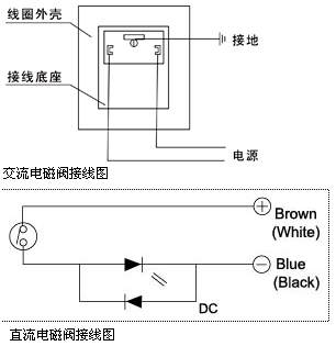
Note:AC does not matter, DC does Positive and negative poles, make sure the voltages are the same.

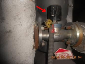
The arrow in the picture below points to the solenoid valve, which is used to control the opening and closing of the air flow channel of the low-pressure rear cylinder water injection system of the turbine.

The low-pressure cylinder water spray system provides condensate water to the nozzles on the spray rings at each end of the dual-flow low-pressure cylinder. When the working conditions of the steam turbine require the low-pressure cylinder water injection system to be put into operation, the solenoid valve in the system is turned on and air is supplied to the actuator of the water injection flow control valve. In this way, the condensed water flows to the nozzle on the exhaust guide ring of the low-pressure cylinder. Moreover, the pressure signal is felt at the condensate pressure measuring point of the pressure controller.
Solenoid valve wiring method:
1. Change the three screws fixing the control board to M4x 35 hexagonal wire posts, fix the solenoid valve control board on the hexagonal wire posts, and add a Pad with insulating paper.
2. Take out the common incoming line of the solenoid valve control board from point B at the incoming end of the motor control board below (point B has less wiring), the main valve output line and the auxiliary valve output line Take them out from their corresponding terminals and enter the explosion-proof junction box (at this time, the connection between the junction box and the power box should be changed from the original four-core to five-core). It merges with a neutral wire in the explosion-proof junction box, and then the three wires enter the solenoid valve together.
3. The auxiliary valve control line (EM2) of the solenoid valve is connected to the TO terminal on the wiring board (or connected to the MT terminal on the motor control board). The main valve control line (EMl) is connected to the OA terminal on the wiring board (at this time, one of the ten 5V groups, ten 12V groups, and ten MT groups between the power box and the wiring board should be changed from the original two-core line to a three-core line ), the two "-" ends of the main and auxiliary valve control lines are connected to the 10 MT group on the motor control board. —"end.
4. Judgment of the main and auxiliary valves of the solenoid valve (of the three lines drawn from the solenoid valve, generally the two-color line is the auxiliary valve line, the brown line is the main valve line, and the blue line is the main valve line. line is zero line):
(1) Wire adjustment method: Since the solenoid valve is a double coil, the lead wire is three cores. If it is four cores, one of them is connected to the valve shell and is the grounding wire. . (You can use the resistance range of a multimeter to measure) its internal wiring. Use the ohm scale of the multimeter (x100) to find out where ① is connected to the neutral line, (the main and auxiliary valve coils have the same resistance) ② and ⑦ are connected to the main and auxiliary valve output lines of the solenoid valve control board respectively. Start the preset oil volume test. If there is a small flow before shutting down, the wiring is correct. If there is no small flow, just replace the ② and ③ wires.
(2) Electrification method: Before installing the solenoid valve, first use the ohm scale of the multimeter (x100) to find out the ① terminal neutral line. The other two wires ② and ③ are the main and auxiliary valve wires. Since the solenoid valve is powered by 220V AC, connect the two wires ①② or ①③ to the 220V power supply.
(3). Determine the main and auxiliary valve coils using the energization method: blow air from the solenoid valve inlet. Generally speaking, the main valve is the main valve. The lead corresponding to ① is connected to the main valve line. The main valve outlet of the solenoid valve control board is the auxiliary valve;the lead wire corresponding to ① is the auxiliary valve line, which is connected to Solenoid valve Just take out the auxiliary valve of the control board.


 WhatsApp: +8615857777578