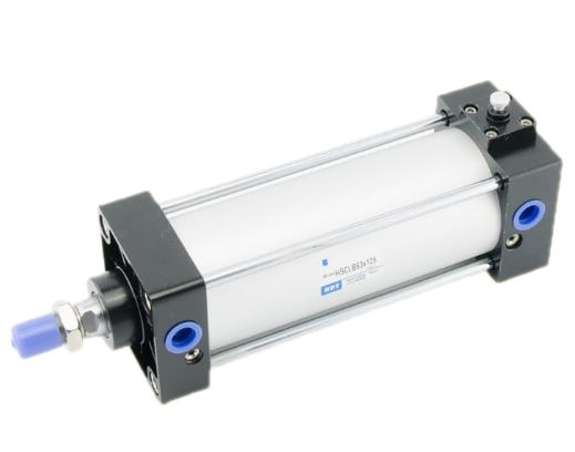
The combined cylinder is the most widely used pneumatic actuator in pneumatic transmission. Generally refers to the gas-liquid damping cylinder, gas-liquid boosting cylinder, etc. formed by the combination of a cylinder and a hydraulic cylinder, which means that when the cylinder piston extends to a certain position, it can be locked and will not extend or retract.
However, generally combined cylinders have a single-stroke output. Although different output strokes can be obtained within the full stroke range through control valves, it is difficult to obtain precise strokes using control valves. position. In some automated production equipment or pneumatic automatic control systems, it is sometimes necessary to combine cylinders to output several precise stroke values to achieve position control of multiple stations of the working mechanism. To meet this requirement, a multi-stroke output digital combination cylinder or a stepper combination cylinder can be used.

The difference between locking cylinders and non-locking cylinders
1. In the locked state, when pressure is provided to port A without the air ports on both sides being pressurized, there is a great danger that the lock is not locked. release, or the lock is suddenly released and the piston rod flies out. When releasing the locking mechanism, be sure to apply pressure to port B and release the locking mechanism when it is not installed.
2. If the quick exhaust valve is used to accelerate the descent, sometimes the cylinder begins to move earlier than the lock pin and cannot be released normally. Therefore, do not use quick exhaust valves for Locking cylinder.
3. Please do not use a three-position solenoid valve: Do not use it in combination with three (especially a metal seal with a middle seal) solenoid valve. If pressure is applied to the port using the side of the locking mechanism, the locking will not work. In addition, sometimes even if it is temporarily locked, the solenoid valveLeaked air will also enter the cylinder, and the lock will be released after a period of time
4. If the locking mechanism side is subject to back pressure, the lock may be released, so please use a single or integrated separate exhaust type solenoid valve.
5. For cylinders with adjustable buffers, if the air cushion valve pin on the side of the locking mechanism is over-tightened, the piston will sometimes be restrained at the end of the stroke, causing damage to the locking mechanism. Therefore, the needle valve should be adjusted so that the piston does not bind.
6. After completing the manual operation of the locking mechanism, be sure to reset the manual device to its original position. In addition, please do not perform manual operations outside the adjustment time, otherwise it may be dangerous.
7. The cylinder should be unlocked during installation and adjustment: if operations such as installation in a locked state are performed, the locking part may be damaged.
8. Please do not use multiple cylinders at the same time: Do not use more than 2 locked cylinders to drive a workpiece at the same time. Sometimes the lock on one of the cylinders cannot be released.
9. Please use the speed control valve under exhaust throttle control: During intake throttle control, the lock may not be released.
10. On the locking side, be sure to use the cylinder stroke terminal: if the piston of the cylinder does not reach the end of the stroke, the lock may not work or the lock may not be released.


 WhatsApp: +8615857777578