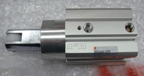
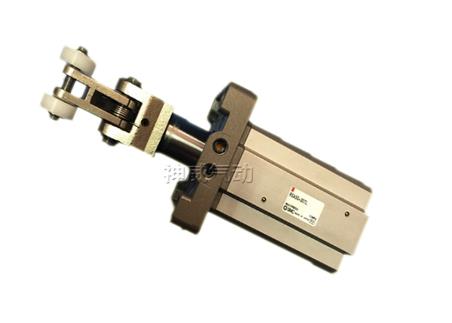
The blocking cylinder is mainly used to stop pallets on the production line, so it is also called Stop cylinder, because its working stroke is fixed, some companies also call it a fixed-range rod cylinder. When the compressed air enters the upper part of the cylinder through the control valve, the piston drives the blocking rod to drop, and the blocked tooling plate is released. When the control valve is deflated, the piston returns under the action of the spring, causing the next tooling plate to be blocked. To change the work position, there is no need to block the tooling plate temporarily. You can manually press down the stop lever and rotate it at an angle to disable the stop lever.
Stop is to stop the movement of an object. In fact, it is also called Blocking cylinder is mainly used to stop pallets on the production line, so it is also called a stop cylinder. Because its working stroke is fixed, Therefore, there are also companies called fixed range rod cylinders. Currently, there are medium-sized, heavy-duty;vertical and horizontal various specifications. Blocking cylinders can be divided into: roller lever type buffering and blocking cylinders, roller type blocking cylinders, direct blocking type blocking cylinders, and horizontal blocking cylinders.

How the stop cylinder works
The cylinder determines the push and pull forces on the piston rod according to the force required for work. Therefore, the cylinder should be selected so that the output force of the cylinder has a slight margin. If the bore diameter is selected to be small, the output force will be insufficient and the cylinder will not work properly;but if the bore diameter is too large, it will not only make the equipment bulky and costly, but also increase air consumption, resulting in a waste of energy. When designing the clamp, a force-increasing mechanism should be used as much as possible to reduce the size of the cylinder. The following is the calculation formula for the theoretical output of the cylinder: F: Theoretical output force of the cylinder (kgf) F′: The output force when the efficiency is 85% (kgf)--(F′=F×85%) D: Cylinder bore (mm) P: Working pressure (kgf/cm2) Example: For a cylinder with a diameter of 340mm, when the working pressure is 3kgf/cm2, what is its theoretical output force? What is the output force? Connect P and D. Find the points on F and F′ and get: F=2800kgf;F′=2300kgf. When selecting the cylinder bore during engineering design, the cylinder bore can be selected based on its operating pressure and theoretical thrust or pulling force.

The structural principle of the stop cylinder: It consists of blade shaft rotor (i.e. output shaft), stator, cylinder block and front and rear end covers. The stator and cylinder are fixed together, and the blades and rotor are connected together. There are two air paths on the stator. When the left path takes in air, the right path exhausts. The compressed air pushes the blades to drive the rotor to swing clockwise. Otherwise, make a counterclockwise swing. The stop cylinder is small in size and lightest in weight, but requires high manufacturing precision, is difficult to seal, has large leakage, and has a large dynamic seal contact area. The frictional resistance loss of the seal is large, and the output efficiency is low, less than 80%. Therefore, its application is limited, and it is generally only used in situations where the installation position is restricted, such as the rotation of fixtures, opening and closing of valves, and table rotation.


 WhatsApp: +8615857777578