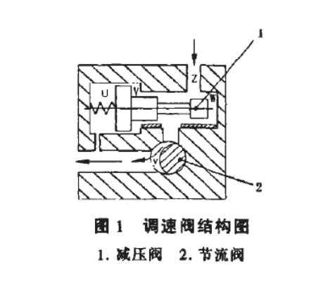
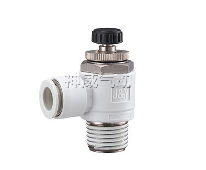
It is a combination valve composed of a fixed differential pressure reducing valve and a throttle valve connected in series. The throttle valve is used to adjust the passing flow, and the constant difference pressure reducing valve automatically compensates for the impact of load changes, so that the pressure difference before and after the throttle valve is a constant value, eliminating the impact of load changes on the flow rate.
The pressure in front and behind the throttle valve is directed to the right and left ends of the pressure reducing valve core respectively. When the load pressure increases, the pressure acting on the left end of the pressure reducing valve core increases. As the hydraulic pressure increases, the valve core moves to the right, the pressure reducing port increases, and the pressure drop decreases, so that the pressure difference of the throttle valve remains unchanged;and vice versa. In this way, the flow rate of the speed control valve is constant (not affected by the load). Speed regulating valveIt can also be designed to throttle first and then reduce pressure.

The working principle of the speed control valve:
The speed regulating valve consists of two parts: a pressure reducing valve and a throttle valve. The throttle valve is connected to the knob to achieve flow control by changing the flow area. When rotating clockwise, the throttle opening y of the throttle valve gradually increases, and the passing flow increases accordingly to control the flow. In the figure, the area of the U cavity at the left end of the pressure reducing valve is equal to the sum of the areas of the V cavity and W cavity. The U cavity is connected to the oil outlet of the throttle, and the V cavity and W cavity are connected to the oil inlet of the throttle. Since the hydraulic pressure plus the spring force at one end of the U chamber is balanced with the sum of the hydraulic pressures on the two areas of the V chamber and W chamber, a certain pressure difference is maintained between the oil inlet and the oil outlet of the throttling gap y. The pressure difference is maintained by spring force. For example, when the pressure at the oil inlet or outlet changes, The pressure difference before and after the throttle valve also changes, and the flow rate will also change accordingly. At this moment, the pressure reducing valve core begins to collapse due to the unbalanced force on both ends. move.
When the outlet pressure of the throttle valve increases, the pressure in the U chamber increases, and the spool of the pressure reducing valve moves to the right, making the pressure reducing throttle port Z open wide and reducing the pressure. The pressure loss at the throttle port decreases, so the inlet pressure of the throttle valve increases until the pressure difference before and after the throttle port y reaches the original set value, the pressure reducing valve core is in a new equilibrium position, and the flow rate also reaches the original setting value. value. On the contrary, when the outlet pressure of the throttle valve drops, the pressure in the U cavity drops, and the spool of the pressure reducing valve moves to the left, making the pressure reducing throttle port smaller and the pressure loss increasing. As a result, the inlet pressure of the throttle valve also drops, causing the throttle port to close. The pressure difference before and after y remains at the original value. In short, no matter how the load changes, the pressure difference before and after the throttle can be kept relatively unchanged, so that the flow rate remains unchanged. In the same way, when the inlet pressure of the speed regulating valve changes, it will be similar to the above process, and the pressure difference at both ends of the throttle valve will be automatically adjusted to keep it unchanged. This type of speed regulating valve is called a pressure compensated speed regulating valve, or speed regulating valve for short.

Performance of speed regulating valve:
General speed control valves do not have temperature compensation and can be used on machine tools, power head slides and similar equipment;the other type has a temperature compensation device and changes the rotary valve core to The slide valve core has a thin blade structure to reduce the impact of temperature on flow. Because the shorter the throttle gap of the throttle valve, the smaller the impact of temperature on flow, this is a flow control valve that is less affected by temperature. Or add a temperature sensing rod made of a highly heat-sensitive material between the adjusting screw and the valve core. When the temperature changes, the thermal expansion and contraction of the valve core are used to automatically adjust the throttling formed between the valve core and the valve body. area. Speed regulating valves with temperature compensation are usually used in equipment that requires high speed regulating performance.


 WhatsApp: +8615857777578