Function and Features
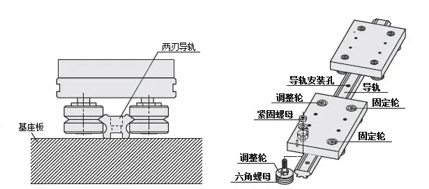
1. The bearing and V-groove (70°) are integrated structures.
2. The special two-edged guide rail has a pedestal, which can be used directly after installing the flat panel.
3. It performs various functions in a mini size.
Basic composition of use cases

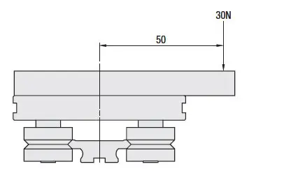
Calculation examples of load and service life< /strong>
Wheel: MVH25
Guide rail: MVR25
As shown in the figure below, it is offset 50mm from the center, and a load of 30N is transported under this condition.


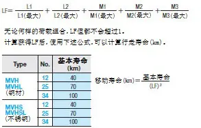
Service life calculation< /span>
The maximum allowable load is to use 4 wheels (2 fixed wheels and 2 adjusting wheels). Each wheel should bear the load evenly.

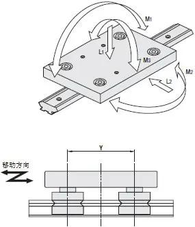
When calculating the service life of the system, the following formula needs to be used to calculate the load factor LF. When considering M1 and M2, calculate by multiplying the value in the table by the distance Y (m) between the wheels.


System assembly and adjustment methods
1. First, install components easily under minimum load conditions.
2. Completely tighten the fixed wheel.
3. Next, temporarily fix the adjustment wheel so that the mounting nut of the adjustment wheel can rotate.
4. Use a wrench to slowly turn the hexagonal nut in the center of the adjustment wheel for adjustment. It is required that there is no play between each set of wheels and the opposite wheel, and a minimum preload is applied.
5. Fix the guide rail, and while the conveyor plate is stationary, check whether the appropriate preload is applied when turning the wheel with your fingers. Although there is a slight resistance, the wheel can still rotate. This level is an appropriate preload. If too much preload is applied, the service life may be affected.
6. Use this method to adjust all the adjustment wheels, and after testing, fully tighten the fastening nuts on the upper part of the wheels according to the recommended torque value.
7. After the adjustment is completed, use the same method as 5 to check again to confirm whether the appropriate preload has been applied.


 WhatsApp: +8615857777578