The following explains the differences between linear bearing shapes (linear type and flange type) and the points to note when assembling them.
(1) Linear and flange types of linear bearings
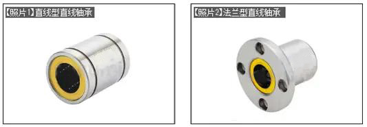
[Photo 1] is a straight type, and [Photo 2] is a flange type.
The flange type bearing of [Photo 2] has the following advantages.
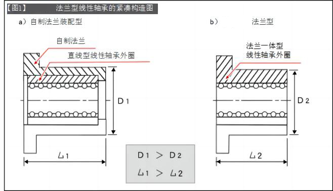
The integrated structure of linear bearings and flange sleeves makes the structure more compact ([Figure 1]).
Compared with linear bearings + separately made flanges, it has the advantages of low price, short delivery period, and stable quality.
[Figure 1] is a diagram illustrating the compact structure of a flange type linear bearing. The linear bearing and flange assembly structure has a long sleeve shape, while the flanged linear bearing adopts an integrated structure and is compact. Enables a compact design that maintains load-bearing performance.
(2) Difference between linear type and flange type
Select linear and flange bearings based on the following content.
Select according to whether the linear bearing can bear force ⇒ Select the flange type for the linear bearing that bears force
Select according to the space and structural surface around the linear bearing assembly ⇒ Reference item - (3 Installation methods and precautions for linear bearings)
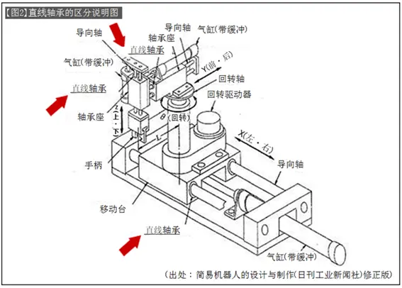
Linear bearings are divided into two types: self-movable structure and fixed bearing to rotate the shaft. [Figure 2] is a structural diagram of an X-Y-Z-θ drive stage using the shaft as a guide axis. It can be classified as follows.

The X-axis movable part in part a) uses a linear bearing to bear the inertia force of the movable body weight, and the linear bearing needs to be tightly fixed.
b) The linear bearing is fixed to the bearing seat. Due to the cylinder drive shaft structure, the axial fixed part of the linear bearing only bears the reaction force of friction, so it adopts a linear compact design. In addition, the installation direction of the Y-axis linear bearing is set in the opposite direction to the rotation axis and the two axes of the θ drive stage, and the linear bearing can also achieve high rigidity with respect to the rotation moment.
Part c) is the same as part b) when viewed from the movable direction of the shaft and will not bear a large force.
(3) Installation methods and precautions for linear bearings
(1) Installation method of linear bearings
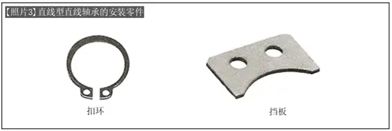
Linear bearings are generally installed using retaining rings or baffles (refer to [Photo 3], [Figure 3]).
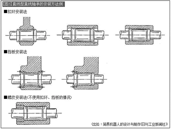
(2) Notes on the installation angle of linear bearings
Linear bearings vary depending on the size and type of shaft diameter and the number of ball rows in the bearing. The number of ball rows of linear bearings is generally 4 to 6 rows arranged at equal angles. When the linear bearing is used in the horizontal direction, the installation angle should avoid the position where the ball row is directly above (left picture of [Figure 4]) as much as possible, because it is easy to generate concentrated load when the ball row is directly above.
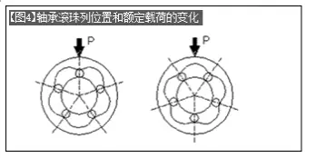
[Figure 4] is a 5-row ball bearing, and its rated load ratio value (right picture ÷ left picture) is as follows. Therefore, you should try to refer to the installation angle in the above picture for installation.
Static load rating
(right picture ÷ left picture) = 1.46
Rated dynamic load
(right picture ÷ left picture) = 1.19


 WhatsApp: +8615857777578