Here we explain the air pressure symbol.
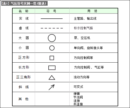
The air pressure symbols are shown in [Table 1] (extracted from JIS symbols), and the purpose of the air pressure components is represented by symbols.

Use the symbols shown in [Table 1] to represent the functions, operating methods, external connection ports, etc. of the pneumatic equipment system.
The pipeline connection lines of the pneumatic equipment system are represented by solid lines.
The control air path is indicated by a dotted line.
It does not represent the structure or arrangement of pneumatic equipment or equipment.
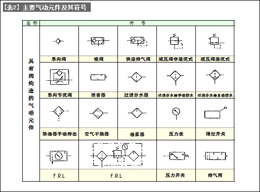
[Table 2] lists examples of symbols for various pneumatic valves. There are many, various devices that can simply be expressed.

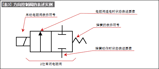
Next, we explain how to express symbols. In actual use, most directional control valves are composed of a complex internal flow path structure, the basic shape of the main body, and an adjustment mechanism. Regarding the basic shape of pneumatic components and the adjustment mechanism, the directional control valve is expressed by combining the symbols in [Table 1]. ([Table 3])

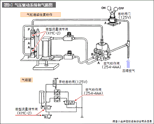
After learning the basics of pneumatic components and pneumatic circuits, the pneumatic drive system can be represented by a simple pneumatic circuit diagram as shown in [Figure 1].


 WhatsApp: +8615857777578