What is a cylinder sensor
The sensor on the cylinder isThe cylinder magnetic induction switch (the cylinder piston ring must be equipped with a magnetic ring) .
Cylinder magnetic induction switch is based on the need to control cylinder conditions and detection signals to determine the quantity and installation location. Magnetic induction switches are generally installed at both ends of the cylinder's stroke;three magnetic switches are installed on a cylinder, which is to obtain a detection signal when it reaches the middle position of the stroke, so that the cylinder stops moving forward at this time, or switches to slow speed , or immediately and quickly, or the detected signal is sent to other actuators for other actions, or other useful signals, etc. Control needs. It doesn't necessarily have to show movement on your cylinder.
There are also magnetic switch settings that install one (only need to obtain one detection signal), and some that install several (need to detect sensing signals from more positions).
How the cylinder sensor works
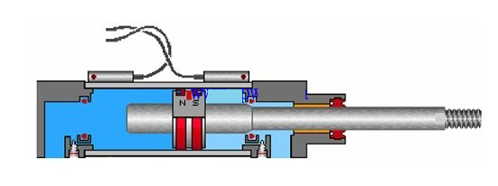
This is a magnetic induction switch with a normally open point. There are magnetic rings above and below the piston inside the cylinder. When the piston moves to the switch position, the magnetism causes the switch to close.
Cylinder sensor (cylinder magnetic induction switch) wiring diagram
The cylinder magnetic switch is used to detect the position of the cylinder piston, that is, to detect the movement stroke of the piston. It can be divided into two types: contact type (magnetic reed tube type with contacts) and contactless type (non-contact transistor type)
Species.
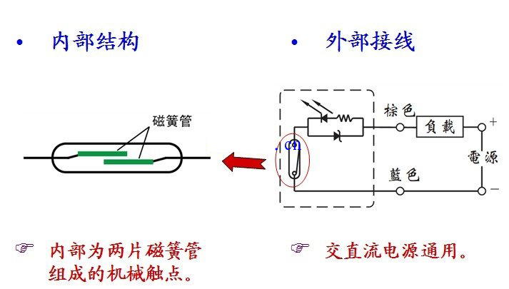
The contact reed tube type has a mechanical contact composed of two reed tubes inside, and is suitable for AC and DC power supplies.

When the magnetic ring moving with the cylinder approaches the induction switch, the two magnetic reeds of the induction switch are magnetized and the contacts are closed, generating an electrical signal;when the magnetic ring leaves the magnetic After the switch, the reed loses its magnetism, the contacts are brokenopen, and the electrical signal disappears. This allows the detection ofcylinderThe piston position thereby controls the corresponding solenoid valve action.

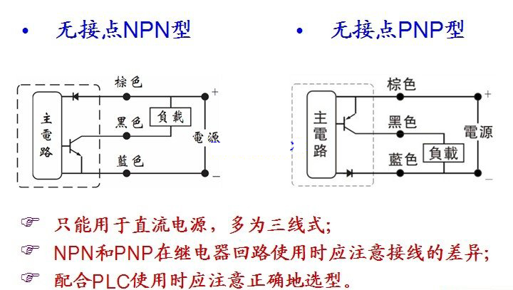
Non-contact transistor type-NPN and PNP types can only be used for DC power supply, most of which are three-wire types;when using NPN and PNP in relay circuits, you should pay attention to the wiring differences;cooperate When selecting PLC, you should pay attention to correctselection.

The contactless sensor switch is essentially different from the contact sensor switch in structure and principle. It sends control signals by controlling the internal transistor. When the magnetic ring is close to the sensor switch
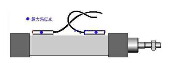
, the transistor is turned on and an electrical signal is generated;when the magnetic ring leaves the magnetic switch, the transistor is turned off and the electrical signal disappears. The maximum sensing point is as shown below.


 WhatsApp: +8615857777578