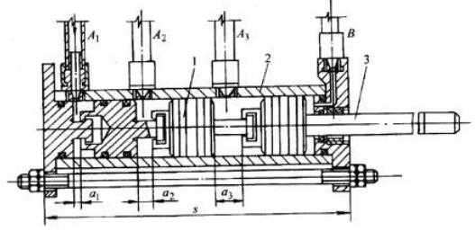
Digital cylinder structure diagram

Digital cylinder
1—piston;2—cylinder;3—piston rod
Digital cylinder< strong>How it works
The right end of the piston has a T-shaped head, and the left end of the piston has a concave hole. The T-shaped head of the rear piston fits into the concave hole of the front piston. Due to the limitations of the cylinder, , the T-head can only move along the cylinder axis in the concave hole, and the two cannot be separated. A number of pistons are placed in the cylinder in series in this order. The range of the T-head's left and right movement in the concave hole is this The amount of stroke of the piston.
Different air inlets A1~Ai (may be A1, or A1 and A2, or A1, A2 and A3, or A1 and A3, or A2 and A3 Etc.) When compressed air (0.4~0.8MPa) is input, the corresponding piston will move to the right. The rightward movement of each piston can push the piston rod 3 to move to the right. Therefore, each time the piston rod 3 moves to the right The total distance is equal to the sum of the strokes of each piston. Here, hole B is always connected to the low-pressure gas source (0.05~0.1MPa). When holes A1~Ai are exhausted, the piston will automatically return to its original position under the action of low-pressure gas.
The stroke size of each piston can be selected in geometric progression from small to large according to the required total stroke s. Assume s=35mm and use 3 pistons, then the strokes of each piston are α1=5mm;α2=10mm;α3=20mm. For example, if s=31.5mm, 6 pistons can be used, then α1, α2, α3, and α6 are designed to be 0.5, 1, 2, 4, 8, and 16mm respectively. By combining these values, it can be within the range of 0.5 to 31.5mm. Get any output displacement amount that is an integer multiple of 0.5mm. And the α1, α2, α3 and αi here can be designed into various different sequence according to the needs, and you can getCylinderThe stroke amount of various required values.


 WhatsApp: +8615857777578