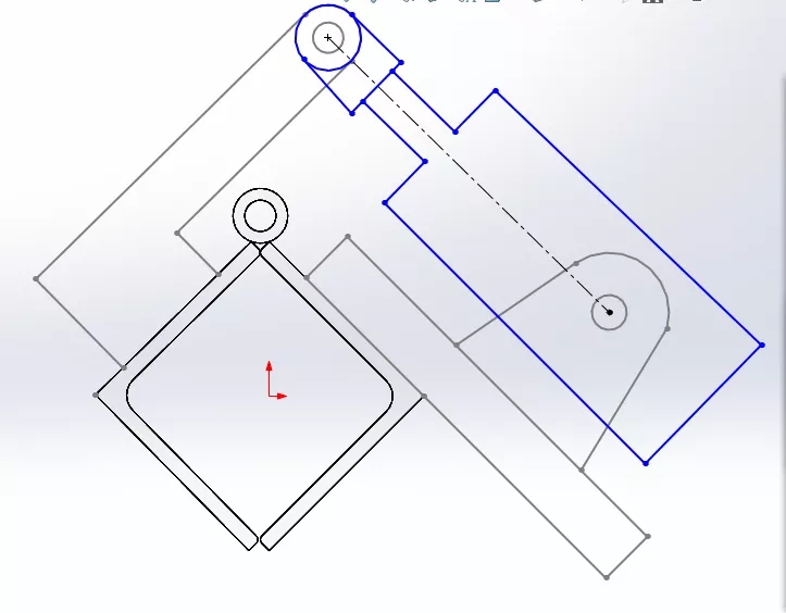
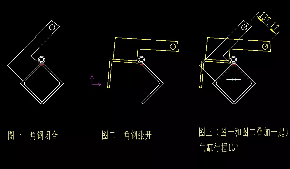
Question: Now I am using sw to draw two angle steel models, then insert new parts into the assembly, and initially draw a cylinder swing arm. How do I open and close the angle steel ( The right angle steel is fixed, the left angle steel rotates with the hinge as the center of the circle, and the swing arm swings accordingly), and the positions of the two working states of the swing arm are quickly obtained, thereby obtaining the cylinder stroke (the two angle steels are generated with weldments and installed in In the assembly. Others are just sketches during preliminary design, drawn by inserting new parts). As shown in the caxa screenshot below, by rotating a sketch block and copying them together, you can measure the hole distance of 137 at the two positions, which is the cylinder stroke length?
In addition: How is the cylinder stroke generally determined through sw modeling when the workpiece rotates? Thanks! Supplement: Maybe I am not clear about what I said, but I just want to ask how to use the SolidWorks modeling sketch design stage in the picture above to achieve results similar to caxa in the picture below?
It is very simple to draw the cylinder stroke in caxa. How to draw the cylinder stroke in SolidWorks? It is impossible to draw a model built with SolidWorks in caxa again...


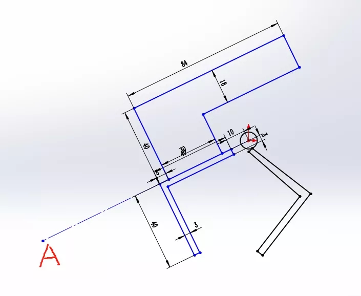
You have obtained the cylinder stroke by drawing the diagram. If you want to calculate, during the extension and retraction of the cylinder piston rod, the angle steel on the left rotates around point a in the figure. In the figure, ab=bc calculates the angle of ab and bc to calculate the length of bc. In addition, the angle steel side length and angle steel rotation angle should be known.
The tail of the angle steel with handle is not in a straight line and cannot be directly insertedCylinder needs to be connected with another rod in the middle, a universal joint. You can't calculate it directly, you have to add something, otherwise have you ever seen a cylinder push rod that curves?
Drag point A of the construction line, and the blue part can be rotated to the position you want as a whole.


 WhatsApp: +8615857777578