Select a controller with a setting range of (0.05~2.5) MPa, and the upper limit switching value is required to be 2.0MPa.
1. Loosen the locking device and screw the pressure controller into the threaded interface of the calibration bench;open the cover and insert the cable through the cable interface into the terminal board. Connect the other end of the cable to a multimeter;
2. Pressurize to 2.0MPa. This value can be read from a standard pressure gauge;turn the setting value adjustment screw clockwise to make the setting value decrease from large to small. The micro switch switches at 2.0MPa.
3. Turn the locking device to adjust the pressure of the calibration bench so that it changes up and down 2.0MPa. When the calibration pressure rises, check whether the switching value is 2.0MPa. This value is the required upper switching value, and this value minus the switching difference (about 0.085MPa) is the lower switching value.
Adjustment method for pressure controller setting value to lower switching value< br />
Also choose a controller with a setting range of (0.05~2.5) MPa, but the pressure is required to drop to 1.8MPa (this value is the lower switching value) to send out a contact signal.
1. Loosen the locking device and screw the pressure controller into the threaded interface of the calibration bench;open the cover and insert the cable through the cable interface into the terminal board. Connect the other end of the cable to a multimeter.
2. Pressurize to 1.8MPa. This value can be read from a standard pressure gauge;turn the setting value adjustment screw counterclockwise to increase the setting value from small to large. The micro switch switches at 1.8MPa.
3. Turn the locking device to adjust the pressure of the calibration bench so that it changes up and down at 1.8MPa. When the calibration pressure drops, check whether the switching value is 1.8MPa. , this value is the required lower switching value, and this value plus the switching difference (about 0.85MPa) is the upper switching value.
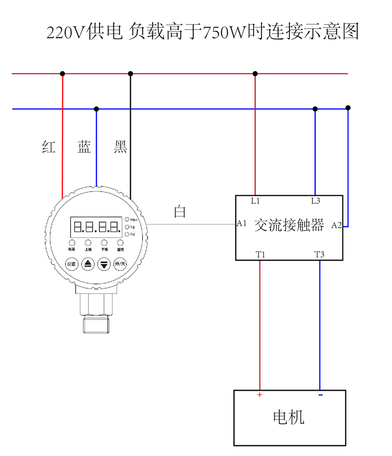
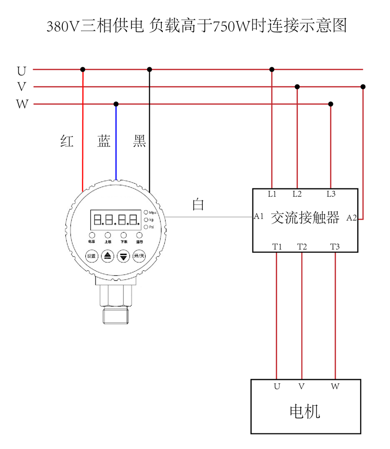
Pressure controller wiring diagram
Working method: When the pressure rises to the set upper limit pressure, the black line and the white line are disconnected. When the gear pressure drops to the lower limit pressure, the gap between the black line and the white line conduction.
Pressure controller can turn on the reverse control function in the system function to achieve reverse control: start at high pressure and stop at low pressure.
220V power supply, connection diagram when the load is higher than 750W:

380V three-phase power supply, connection diagram when the load is higher than 750W:


 WhatsApp: +8615857777578