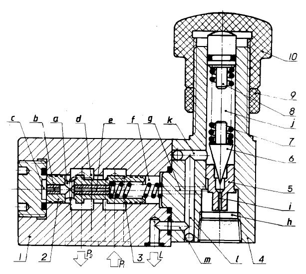
Pressure reducing valvesThere are two types: direct-acting and pilot-operated. The pilot-operated type is generally used. The following figure shows the structure diagram of the pilot pressure reducing valve, which consists of two parts. That is, the pilot valve regulates pressure and the main valve reduces pressure.

During operation, hydraulic oil enters from the oil inlet P1, flows through the main valve gap to the oil outlet P2, and is sent to the actuator. There is an axial groove b at the left end of the main valve core, and a small damping hole e in the center of the valve core. The pressure reducing oil can pass through the groove a, the damping hole e, the oil chamber f and the hole g to the lower end of the pilot valve and to the poppet valve. An upward hydraulic force. When the load is small and the oil outlet pressure is less than the set pressure, the poppet valve does not open. The oil pressure at the left and right ends of the main valve core is equal. The main valve core is pressed to the lowest position under the action of the balance spring, and the main valve core and the valve body form a The slit d is the largest, and the pressure loss is minimal when the oil flows through. At this time, the pressure reducing valve is in a non-working state and is normally open. When the load is large and the oil outlet pressure reaches the set pressure, the poppet valve opens and the control oil begins to flow. Oil flows through the damping hole e on the main spool, causing a pressure drop, causing the oil pressure at the right end of the main spool to is less than the oil pressure at the left end, the main valve core overcomes the action of the balance spring and moves to the right under the action of the pressure difference, causing the slit d of the main valve port to decrease, resulting in a pressure drop. This pressure drop can be automatically adjusted to stabilize the oil pressure at the oil outlet at the set value. At this time, the pressure reducing valve is in working condition. When the load is greater, the orifice d will be smaller and the pressure drop will be greater, making the oil outlet pressure stable at the set value.
First we need to Hydraulic valveLearn about the types:
Classified by control method: manual, electronic control, hydraulic control;
Classification by function: flow valve (throttle valve, speed regulating valve, diverter and collecting valve), pressure valve (relief valve, pressure reducing valve, sequence valve, unloading valve valve), directional valve (electromagnetic reversing valve, manual reversing valve, one-way valve, hydraulic control one-way valve);
Classified by installation method: plate valve, pipe valve, stacked valve, threaded cartridge valve, cover valve;
Classified by operation method: manual valve, motorized valve, electric valve, hydraulic valve, electro-hydraulic valve, etc.
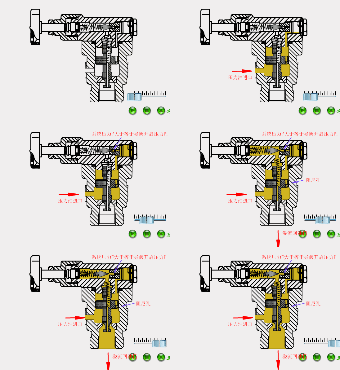
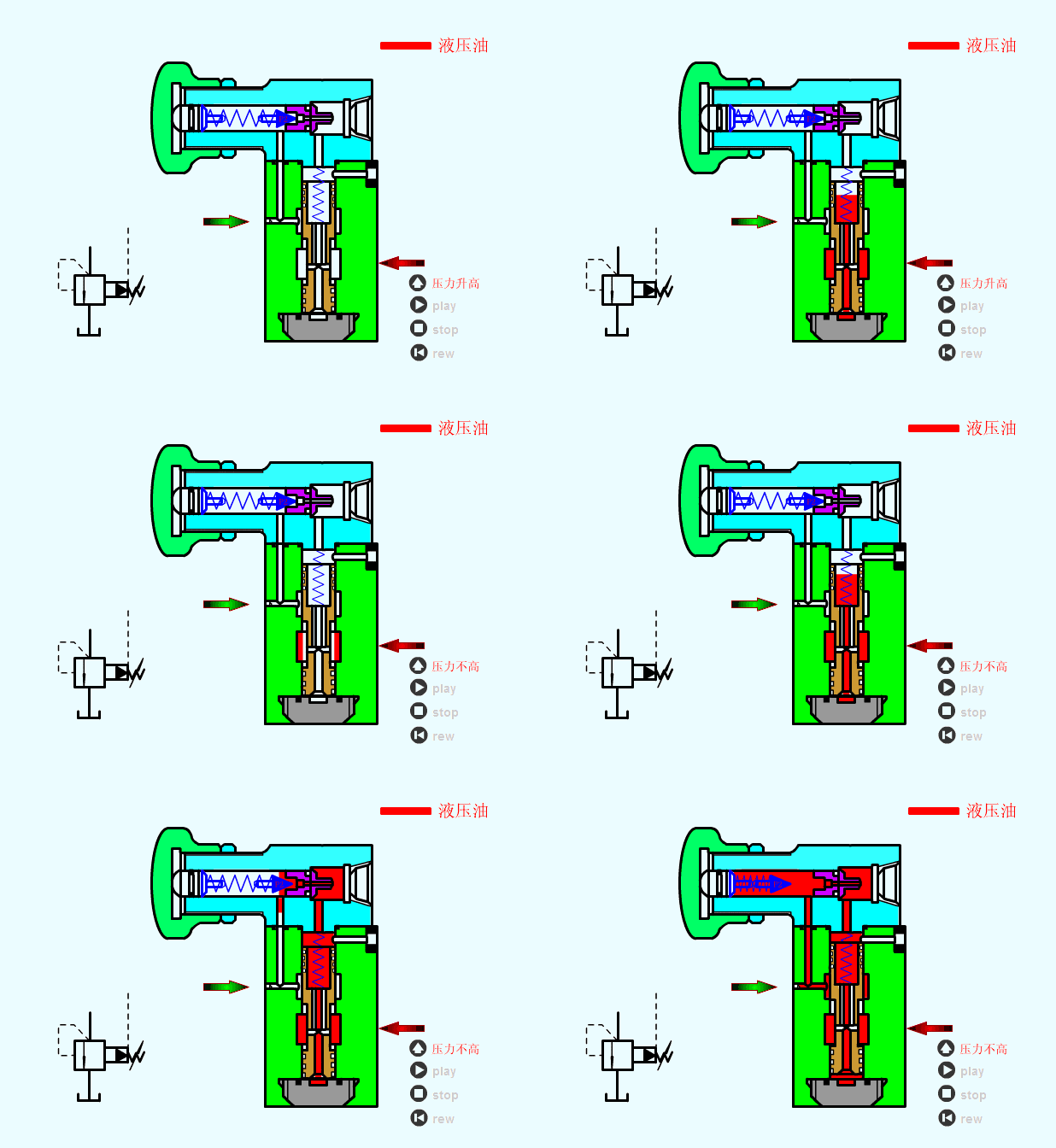
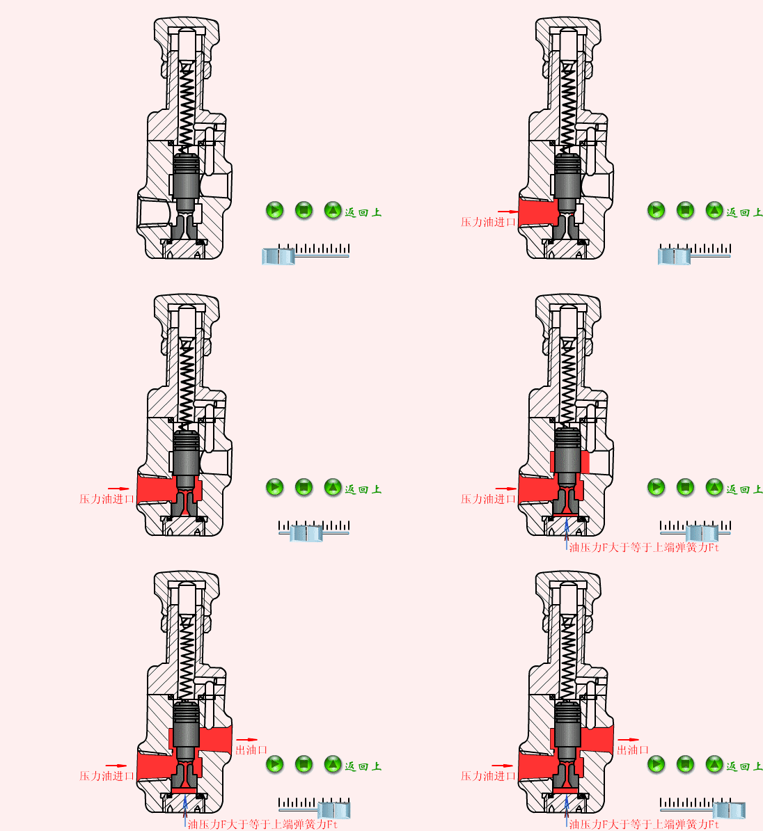
The dynamic demonstration of the working principle of the hydraulic valve is as follows:
1. Pilot relief valve

2. Low pressure relief valve

3. Direct-acting relief valve


 WhatsApp: +8615857777578