1. Purpose of finger cylinder
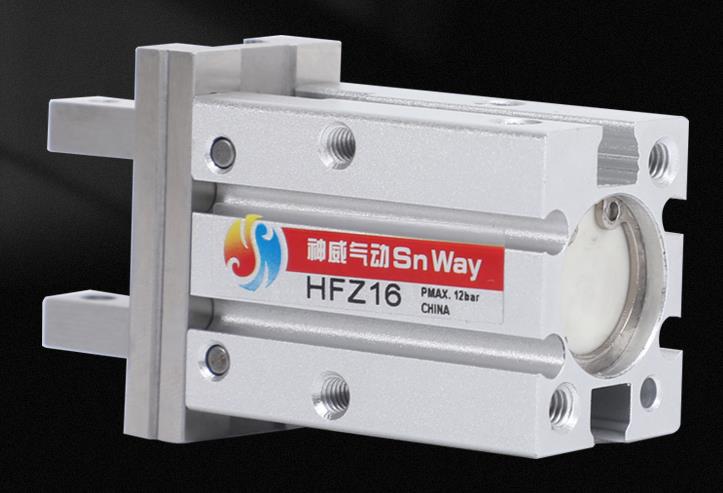
Pneumatic finger, also known as pneumatic gripper or pneumatic gripper finger, is an execution device that uses compressed air as power to clamp or grab workpieces. Originally originated in Japan, it was later widely used by domestic automation companies. According to the style, it can usually be divided into Y-type clamping fingers and flat-type clamping fingers. The cylinder diameter is divided into 16mm, 20mm, 25mm, 32mm and 40MM. Its main function is to replace people's grabbing work, which can effectively improve production efficiency and work efficiency. safety. The SMC Pneumatic Finger Series is one of the most commonly used pneumatic gripper devices in the industrial field.

2. Selection factors of finger cylinder (pneumatic gripper)< br />
1. According to the size, shape, quality and purpose of use of the workpiece, choose the parallel opening and closing type or the fulcrum opening and closing type;
2. Select the series of finger cylinders (air grippers) according to the size, shape, extension, usage environment and purpose of the workpiece;
3. Select the size of the air claw according to the clamping force of the air claw, the distance between the clamping points, the amount of extension and the stroke, and further select the required size according to the needs. options.
3. Characteristics of finger cylinder (air claw)
1. All structures of the finger cylinder are double-acting, capable of bidirectional grabbing, automatic centering, and high repeatability;
2. The grabbing torque is constant;
3. Non-contact detection switches can be installed on both sides of the cylinder;
4. There are multiple installation and linking methods.
4. Working principle of finger cylinder
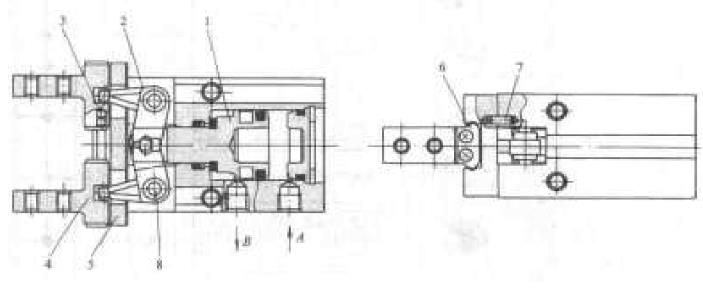
The working principle diagram of the finger cylinder is as follows:

When port A takes in air and port B exhausts, Cylinder The piston rod 1 extends and rotates around the lever shaft 8 through the lever 2, driving the two fingers 4 through a set of steel The ball 3 moves outward in a straight line on the guide rail 5, and the two fingers open to release the workpiece. The stop block 6 limits the finger opening stroke, and the positioning pin 7 ensures that the linear guide rail is not misaligned.


 WhatsApp: +8615857777578