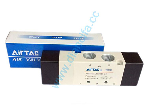
The air control valve includes two, three and five-way, the following three-way Air Control Valve Taking the three-way air control valve as an example, the medium flow direction should be consistent with the direction of the arrow on the valve body. The external pressure-guiding pipe device can pass the pressure test before leaving the factory. It is strictly forbidden to damage the pressure-guiding device during installation;the 1/2 pipe joint on the valve should be installed at the inlet of the water pump;it can be installed horizontally or vertically;the flow-limiting check valve When the required lift is greater than 0.1MPa, first open the four-way counterclockwise.
Then gradually close the pressure regulating valve clockwise. During the closing process, the outlet pressure will gradually increase until the outlet pressure reaches the required lift. The initial adjustment is completed and the water pump is repeatedly started and closed. 2-3 times, running for 3-5 minutes each time, the debugging work is completed when the outlet pressure remains unchanged;the outlet pressure value should be checked frequently depending on the water quality. When the outlet pressure is lower than the set value, the filter should be opened to remove dirt.

Classification of air control valves
The component that controls and regulates the pressure of compressed air is called a pressure control valve;the component that controls and regulates the flow of compressed air is called a flow control valve;the component that changes and controls the direction of the air flow is called a flow control valve. For the directional control valve. In addition to the above three types of control valves, there are also logic components that can achieve certain logic functions, including jet components with no movable parts inside the components and pneumatic logic components with movable parts. In terms of structural principle, the logic element is basically the same as the directional control valve, except that the volume and diameter are smaller. It is generally used to implement the logic operation function of the signal.
With the miniaturization of pneumatic components and the extensive application of PLC control in pneumatic systems, the application scope of pneumatic logic components is gradually decreasing. In terms of control methods, pneumatic control can be divided into two categories: intermittent control and continuous control. In intermittent control systems, pressure control valves, flow control valves and directional control valves are usually used to realize program actions;in continuous control systems, in addition to pressure and flow control valves, servo and proportional control valves are also used. , in order to continuously control the system.
The working principle of air control valve
The mixing outlet of the air control valve is equipped with a heat-sensitive element. The characteristics of the temperature-sensing element are used to push the valve core in the valve body to move, blocking or opening the cold and hot water. water intake. When the cold water is blocked and hot water is turned on, when the temperature adjustment knob sets a certain temperature, no matter how the temperature and pressure of the cold and hot water inlet change, the proportion of cold and hot water entering the water outlet will also change, thus making The outlet water temperature is always kept constant, the temperature adjustment knob can be set arbitrarily within the specified temperature range of the product, and the thermostatic mixing valve will automatically maintain the outlet water temperature.


 WhatsApp: +8615857777578